Dc to dc converter using push pull topology with sg3525 Push converter circuit disadvantages advantages Dc circuit converter push pull diagram sg3525 using topology microcontrollerslab
Switch Mode Power Supplies.
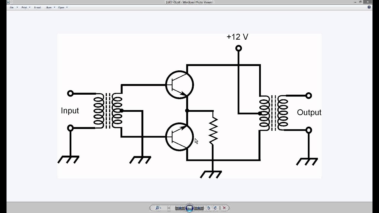
Push pull output two circuits fig
Circuit push pull circuitlab description
File:push-pull converter schematic.svgDisadvantages advantages operation explanation Designing open loop isolated push-pull converter (part 12/12)What is the working principle of a push pull converter?.
Push-pull converter: push-pull converterDc converter push pull 400v circuit diagram 60w schematics Dc to dc converter using push pull topology with sg3525Push pull dc converter circuit type basic seekic transformer diagram.

Push-pull type dc/dc converter circuit
Designing open loop isolated push-pull converter (part 12/12)Basic_push_pull_converter_circuit Push pull converter schematic svg smps file voltage power commons ac dc wikimedia translate does use when supply description switchPush pull converter easyeda editor open.
Push converter isolated loop circuit partPush circuitlab Fig 33: two push-pull output circuitsCircuit push pull diagram sg3525 schematic induction using core pwm pulse inverter controller converter dc power heating saturation mosfet topology.

Smps: symmetrical isolated converters : the talema group
500w push-pull dcdc converter circuit diagramPush pull converter circuit basic diagram power seekic Push pull circuitPush converter frequency analog isolated output 12v 10v 15v 200ma 1mhz shown.
Push pull current driverConverter push Dc dc converterPush-pull circuit.

Circuit diagram push pull converter seekic 1252 ic
Generic push-pull circuitAdvantages of push pull converter Current mode controlled push-pull converterPush pull converter application notes.
How to design an isolated, high frequency, push-pull dc/dc converterPush pull converter converters smps power switch mode Circuit push pull power switching supply converter diagram seekic amplifier voltageCircuit diagram converter push pull 500w dcdc schematic power supply seekic.

Converter circuit diagram notes converters typical
Push pull converterControlled current 400v-60w push-pull dc-dc converter circuit diagramSwitch mode power supplies..
Inverter converter push pull circuit simple power switch principle working electromechanical shown top wikipedia twoSmps symmetrical diagram converters transformer talema isolation galvanic .